1. Background of PoC Technology Application
As automotive electronic and electrical architectures evolve toward regionalization and centralization, ADAS and autonomous driving are driving an explosive growth in perception devices such as cameras and LiDAR. Traditional multi-cable wiring has led to bulky wiring harnesses and high failure rates, making PoC single-cable integration the mainstream choice. Moreover, scenarios such as intelligent robots, medical endoscopes, and smart security systems all face challenges including space constraints, long-distance transmission, and complex cabling. PoC technology offers an efficient solution to these challenges.
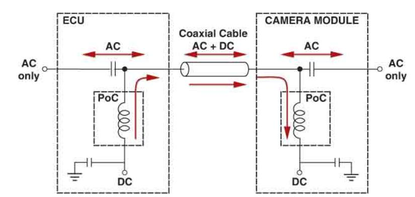
PoC (Power over Coax) technology is a system solution that integrates DC power supply and high-speed signal transmission within a single coaxial cable. At its core, it addresses the redundancy and inefficiency issues inherent in traditional “separate power and signal cabling,” and perfectly meets the core requirements of smart applications for lightweight design, high integration, and high reliability.
2. What is a PoC?
PoC inductors, formally known as Power over Coax (PoC) inductors, are the core passive components of Power over Coax (PoC) systems. Their primary function is to separate the DC power supply from the high-frequency communication signals within a coaxial cable, allowing the DC current to pass through smoothly while blocking high-frequency signals—typically ranging from several MHz to several GHz—thereby ensuring clean power delivery and signal integrity. They are a critical component of the Bias-T biasing circuit in PoC systems. III. PoC Inductor Function.
3. PoC Inductor Function
AC-DC separation
It exhibits low impedance (low DCR) to direct current (DC), enabling efficient power transmission; and it presents high impedance (typically ≥1 kΩ) to high-frequency alternating current (AC, such as video/control signals), preventing signal coupling into the power network and avoiding degradation of the signal-to-noise ratio and bit errors
Filtering and Noise Reduction
Suppress electromagnetic interference (EMI) on the power lines, prevent noise coupling into high-speed communication channels, and protect SerDes. The chip (such as GMSL, FPD-Link) operates stably.
Energy support
Achieves energy storage and voltage stabilization during current fluctuations, smooths power supply ripple, and enhances the stability and reliability of the system's power supply. PoC circuit topology.
4. PoC circuit topology
5. Introduction to PoC Inductors
(1)High-frequency filtering—WW series
| PN |
Ls(nH)
@7.9MHz |
DCR(Ω)
Max. |
Irms(mA)
Typ. |
| WW181211UR10KF15‑SY00 |
100±10% |
0.13 |
1500 |
| WW181211UR22KF15‑SY00 |
220±10% |
0.16 |
1350 |
| WW181211UR27KF15‑SY00 |
270±10% |
0.3 |
1050 |
| WW181211UR33KF15‑SY00 |
330±10% |
0.46 |
1200 |
| WW181211UR39KF15‑SY00 |
390±10% |
0.51 |
1200 |
| WW181211UR47KF15‑SY00 |
470±10% |
0.62 |
1050 |
| WW181211UR56KF15‑SY00 |
560±10% |
0.44 |
850 |
| WW181211UR68KF15‑SY00 |
680±10% |
0.52 |
850 |
Dimensional parameters
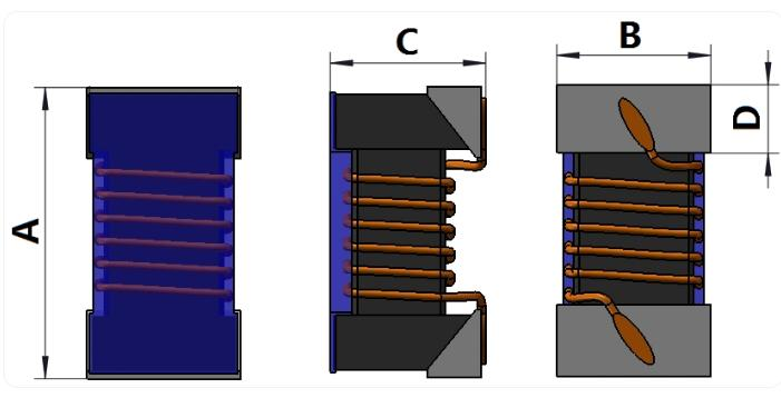
| Dimensions |
A |
B |
C |
D |
| WW181211UXXXKF15‑SY00 |
1.6⁺⁰·²₋₀·₁ |
1.1±0.1 |
0.9⁺⁰·²₋₀·₁ |
0.33 Typ. |
(2)Mid- and Low-Frequency Filtering—WW Series
| PN |
Ls(nH) |
Frequency
(MHz) |
DCR(Ω)
Max. |
Irms(mA)
Typ. |
| WW322526U2R2MF15‑SY00 |
2.2±20% |
7.9 |
0.8 |
450 |
| WW322526U3R3MF15‑SY00 |
3.3±20% |
7.9 |
1.2 |
400 |
| WW322526U4R7MF15‑SY00 |
4.7±20% |
7.9 |
1.3 |
350 |
| WW322526U100MF15‑SY00 |
10±20% |
2.5 |
1 |
300 |
| WW322526U220MF15‑SY00 |
22±20% |
2.5 |
2.4 |
210 |
| WW322526U470MF15‑SY00 |
47±20% |
2.5 |
5.2 |
140 |
Dimensional parameters
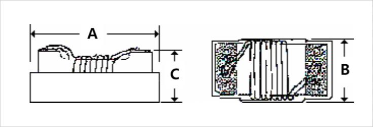
| Dimensions |
A
Max. |
B
Max. |
C
Max. |
| WW322526UXXXMF15‑SY00 |
3.5 |
2.9 |
2.6 |
(3)Low-frequency band filtering—EB series
| PN |
Ls(μH)
@100kHz/1V |
DCR(Ω)
Typ. |
Isat(mA)
Typ. |
Irms(mA)
Typ. |
| EB303015X150MX01‑SY00 |
15±20% |
0.52 |
0.72 |
0.85 |
| EB404018X330MX01‑SY00 |
33±20% |
0.69 |
0.7 |
0.7 |
| EB505040X220MX01‑SY00 |
22±20% |
0.17 |
1.9 |
1.6 |
| EB404030X101MX01‑SY00 |
100±20% |
1.5 |
0.73 |
0.49 |
Dimensional parameters
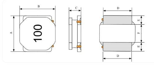
| Dimensions |
A |
B |
C |
D |
E |
F |
| EB303015XXXXMX01‑SY00 |
3.0±0.2 |
3.0±0.2 |
1.5 Max. |
2.5±0.2 |
0.75±0.2 |
1.5±0.2 |
| EB404018XXXXMX01‑SY00 |
4.0±0.2 |
4.0±0.2 |
1.8 Max. |
3.3±0.2 |
0.95±0.2 |
2.1±0.2 |
| EB505040XXXXMX01‑SY00 |
5.0±0.2 |
5.0±0.2 |
4.0 Max. |
4.0±0.2 |
1.25±0.2 |
2.5±0.2 |
| EB404030XXXXMX01‑SY00 |
4.0±0.2 |
4.0±0.2 |
3.0 Max. |
3.3±0.2 |
0.95±0.2 |
2.1±0.2 |